|
Size: 4832
Comment:
|
Size: 4836
Comment:
|
| Deletions are marked like this. | Additions are marked like this. |
| Line 33: | Line 33: |
| $$ \Large F_T = X ( 1 - \sin( \theta ) ) ~ { B_{max}^2 \over { 2 \mu_0 } } $$ | $$ \Large F_T ~=~ X ~ ( 1 - \sin( \theta ) ) ~ { B_{max}^2 \over { 2 \mu_0 } } $$ |
Trapezoid Bolt
Simplification in progress ...
The launch loop rotor is composed of separable bolts, mostly made of thin laminations of transformer steel, along with carbon fiber stiffeners, embedded aluminum induction motor conductors, and a central spine. The bolts are normally used in two modes; assembled into a multilobed rotor for the main tracks and inclines, and separated into separate bolts for minimum radius deflection.
The number of lobes in the rotor (and the number of bolts in parallel) remains to be determined; probably 4 or 6. The length of the bolts also will be determined later; gaps between lengths will change with velocity, and the gaps will interrupt the motor field and cause some vibration in the vehicle sked. The size and cross section of the rotor is constrained by its linear density; the current estimate is 43.2 grams per centimeter of rotor length, or 4.32 kg per meter.
Rotor Mode
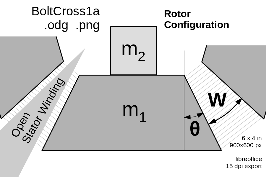
The angle of the faces can be computed from the geometry of the assembled rotor, and the stator wedge shape of the stator windings and the wedge-shaped stator winding gaps penetrating it. (Note 1) If there are N lobes, and the stator wedges have an angle of W degrees, then the angle of both faces of the trapezoidal bolt are 360/N-W, and the angle on each face is half that, θ = 180/N - W/2. Here's some plausible bolt face angles:
Stator |
Bolt face angle θ |
||||
N=3 |
N=4 |
N=5 |
N=6 |
||
0° |
60° |
45° |
36° |
30° |
|
10° |
55° |
40° |
31° |
25° |
|
20° |
50° |
35° |
26° |
20° |
|
30° |
45° |
30° |
21° |
15° |
|
Deflection Mode
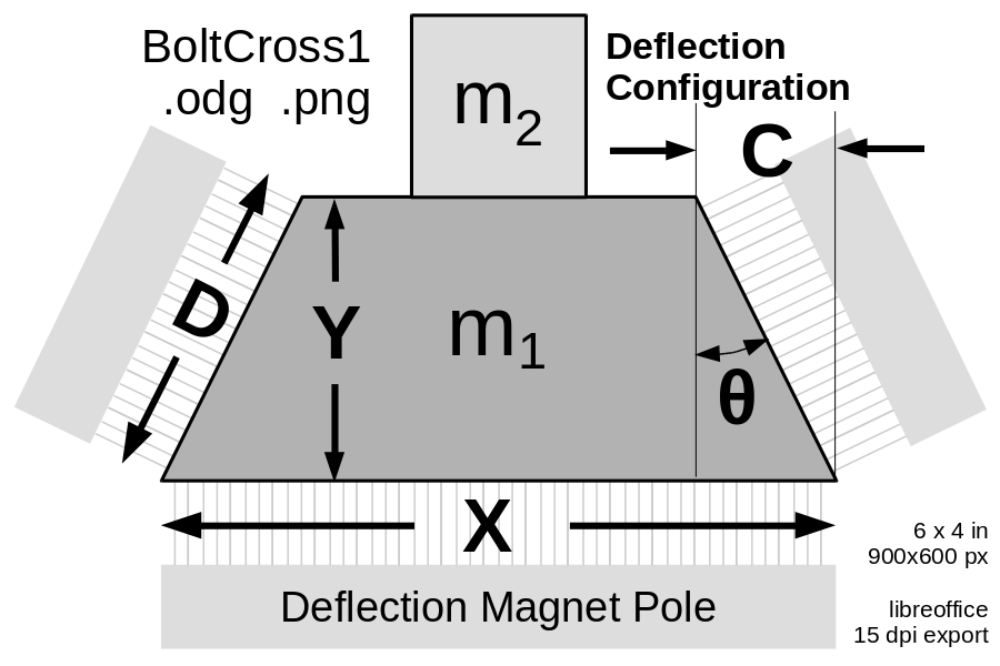
The radius of the ambit and upturn deflection magnets are constrained by acceleration, rotor mass density, and maximum deflection force. An electromagnet pole (shown at the bottom of this diagram) pulls the rotor towards it, with near-saturation flux density B_{max} , perhaps 1.8 Tesla. The material will be strongly saturated and with considerable hysteresis at this field strength; hysteresis helps regulate the deflection force, though it increases the controller power necessary to modify it.
For a 4.32 kg/m rotor with six bolts arranged in a hexagon, each bolt will mass 7.2 grams per centimeter of length. If 30% of the bolt mass is non-iron mass m₂, and 70% of the bolt is m₁, then m₁ is approximately 5 g/cm = 5e-3 kg/m.
The density of 4% silicon transformer steel is 7.65 g/cm³, so A₁, the cross section of the area with mass m₁, is A₁ = 0.65 cm² = 6.5e-5 m².
An electromagnet pole (shown at the bottom of this diagram) pulls the rotor towards it, with near-saturation flux density B_{max} , perhaps 1.8 Tesla. The material will be strongly saturated and with considerable hysteresis at this field strength; that actually helps regulate the deflection force.The widest, thinnest rotor iron is easiest to deflect, however, the flux on face X must exit through the two faces D, constraining minimum bolt iron height. |
The (atttracting) deflection force at the bottom is F_X ~=~ X ~×~ B_{max}^2 / 2 \mu_0 so FX = X × 1.29 MPa . The force at each diagonal face is half that. The fraction of the force directed upwards is F_X sin 0, twice the upwards force at each side face. So, the total downwards deflection force is:
Note 1: The spacing between hyperspeed rotor and the wire stator must be maintained actively by globally aware electronics. If the stator contacts the rotor in any channel anywhere along the 6000 km length of the rotor, the rotor and stator will be vaporized and the entire launch loop will fail. This is almost impossible, and will only become possible after years of development and high volume deployment of lower speed power storage loops. Technology evolves, and intermediate evolutionary steps and accumulated experience is required. Spacing control will require redundant electronics, and some means of rapidly withdrawing short sections of stator outwards from the bolt stream if any anomalies are detected.


