|
Size: 3597
Comment:
|
Size: 3534
Comment:
|
| Deletions are marked like this. | Additions are marked like this. |
| Line 16: | Line 16: |
| The angle of the faces can be computed from the geometry of the assembled rotor, and the stator wedge shape of the stator windings and the plenums penetrating it. If there are N lobes, and the stator wedges have an angle of W degrees, then the angle of both faces of the trapezoidal bolt are 360/N-W, and the angle on each face is half that, 180/N - W/2. Here's some plausible face angles: | The angle of the faces can be computed from the geometry of the assembled rotor, and the stator wedge shape of the stator windings and the plenums penetrating it. If there are N lobes, and the stator wedges have an angle of W degrees, then the angle of both faces of the trapezoidal bolt are 360/N-W, and the angle on each face is half that, 180/N - W/2. Here's some plausible bolt face angles: |
| Line 18: | Line 18: |
| || ||<-4> Bolt face angles || | |
| Line 20: | Line 21: |
| ||<)> 4° ||<)> 58° ||<)> 43° ||<)> 34° ||<)> 28° || ||<)> 8° ||<)> 56° ||<)> 41° ||<)> 32° ||<)> 26° || ||<)> 12° ||<)> 54° ||<)> 39° ||<)> 30° ||<)> 24° || ||<)> 16° ||<)> 52° ||<)> 37° ||<)> 28° ||<)> 22° || |
||<)> 10° ||<)> 55° ||<)> 40° ||<)> 31° ||<)> 25° || |
| Line 25: | Line 23: |
| ||<)> 30° ||<)> 45° ||<)> 30° ||<)> 21° ||<)> 15° || |
Trapezoid Bolt
The launch loop rotor is composed of separable bolts, mostly made of thin laminations of transformer steel, along with carbon fiber stiffeners, embedded aluminum induction motor conductors, and a central spine. The bolts are normally used in two modes; assembled into a multilobed rotor for the main tracks and inclines, and separated into separate bolts for minimum radius deflection. |
Deflection Mode
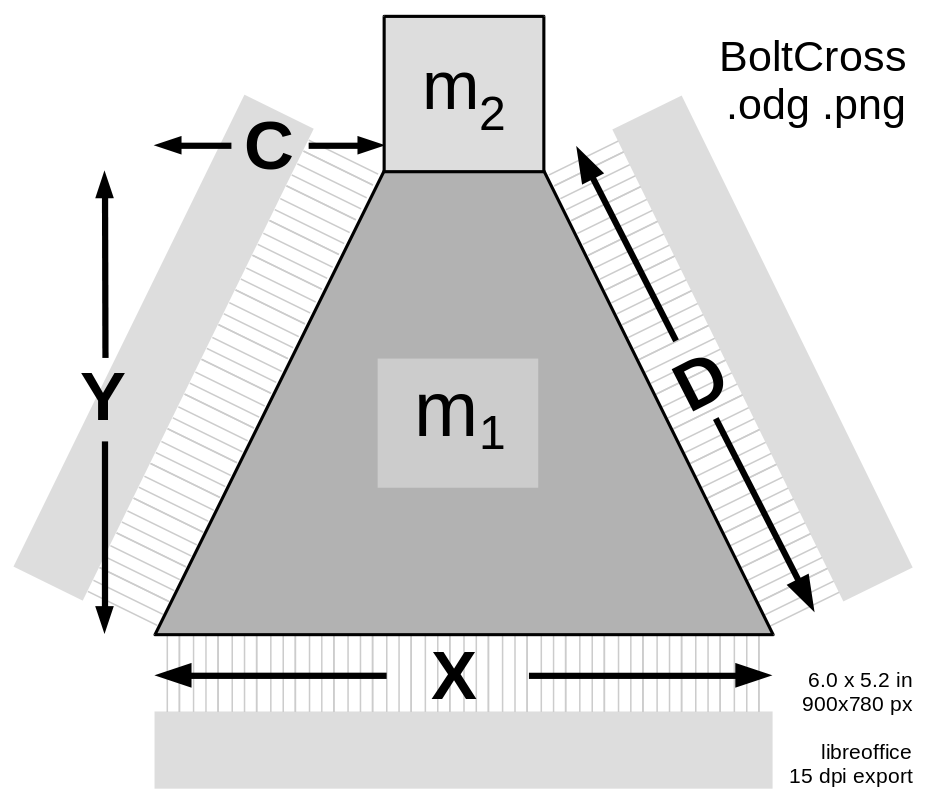
In deflection mode, an electromagnet pole (shown at the bottom of this diagram) pulls the rotor towards it, with near-saturation flux density B_{max} , perhaps 1.8 Tesla. The material will be strongly saturated and with considerable hysteresis at this field strength; that actually helps regulate the deflection force.
The deflection field "entering" at the bottom exits at the two diagonal pole faces, with less flux density. The (atttracting) deflection force at the bottom is F_X ~=~ X ~×~ B_{max}^2 / 2 \mu_0 so FX = X × 1.29 MPa . The flux at each diagonal face is B_D = ( X / 2 D ) B_{max} so the force at each face is F_D ~=~ D ~×~ B_D^2 / 2 \mu_0 ~=~ D ~×~ (X/2D)^2 B_{max}^2 / 2 \mu_0 ~=~ X^2/D × B_{max}^2 / 8 \mu_0 so FD = X²/D × 0.16 MPa .
Note that the flux B_D cannot exceed B_{max} , so D > X/2 . The bolt cannot be very thin in the Y direction.
A fraction C/D of that force is directed upwards for each face; the total upward force through both faces is FC = 2 C (X/D)² × 0.16 MPa.
The angle of the faces can be computed from the geometry of the assembled rotor, and the stator wedge shape of the stator windings and the plenums penetrating it. If there are N lobes, and the stator wedges have an angle of W degrees, then the angle of both faces of the trapezoidal bolt are 360/N-W, and the angle on each face is half that, 180/N - W/2. Here's some plausible bolt face angles:
|
Bolt face angles |
|||
W |
N=3 |
N=4 |
N=5 |
N=6 |
0° |
60° |
45° |
36° |
30° |
10° |
55° |
40° |
31° |
25° |
20° |
50° |
35° |
26° |
20° |
30° |
45° |
30° |
21° |
15° |
Since D² = Y² + C² = (A₁/(X-C))² + C² , the total downward deflection force is:
This deflects mass m₁ + m₂, so the total radial acceleration is ay = Fy/( m₁ + m₂ ), which we hope to maximize by optimizing X and C, given A₁.

