|
Size: 756
Comment:
|
Size: 756
Comment:
|
| Deletions are marked like this. | Additions are marked like this. |
| Line 3: | Line 3: |
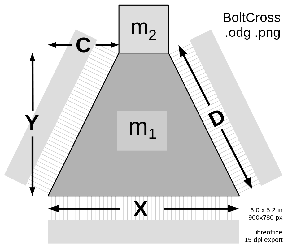
| || [[ attachment:BoltCross.png | {{ attachment:BoltCross.png | | width=200 }} ]] || The launch loop rotor is composed of separable bolts, mostly made of thin laminations of transformer steel, along with carbon fiber stiffeners, embedded aluminum induction motor conductors, and a central spine. The bolts are normally used in two modes; assembled into a multilobed rotor for the main tracks and inclines, and separated into separate bolts for minimum radius deflection. <<BR>><<BR>>The number of lobes in the rotor (and the number of bolts in parallel) remains to be determined; probably between 4 and 6. The length of the bolts may also change. The size and cross section is constrained by the linear density of the rotor. || | || [[ attachment:BoltCross.png | {{ attachment:BoltCross.png | | width=400 }} ]] || The launch loop rotor is composed of separable bolts, mostly made of thin laminations of transformer steel, along with carbon fiber stiffeners, embedded aluminum induction motor conductors, and a central spine. The bolts are normally used in two modes; assembled into a multilobed rotor for the main tracks and inclines, and separated into separate bolts for minimum radius deflection. <<BR>><<BR>>The number of lobes in the rotor (and the number of bolts in parallel) remains to be determined; probably between 4 and 6. The length of the bolts may also change. The size and cross section is constrained by the linear density of the rotor. || |
Trapezoid Bolt
The launch loop rotor is composed of separable bolts, mostly made of thin laminations of transformer steel, along with carbon fiber stiffeners, embedded aluminum induction motor conductors, and a central spine. The bolts are normally used in two modes; assembled into a multilobed rotor for the main tracks and inclines, and separated into separate bolts for minimum radius deflection. |

