|
Size: 1738
Comment:
|
Size: 1980
Comment:
|
| Deletions are marked like this. | Additions are marked like this. |
| Line 12: | Line 12: |
| The deflection field "entering" at the bottom exits at the two diagonal pole faces, with less flux density. The deflection force at the bottom is $ F_A ~=~ A ~×~ B_{max}^2 / 2 \mu_0 = ~$ A × 1.29 MPa . | The deflection field "entering" at the bottom exits at the two diagonal pole faces, with less flux density. The (atttracting) deflection force at the bottom is $ F_A ~=~ A ~×~ B_{max}^2 / 2 \mu_0 ~=~ $ A × 1.29 MPa . The flux at each diagonal face is $ B_D = ( A / 2 D ) B_{max} $ so the force at each face is $ F_D ~=~ D ~×~ B_D^2 / 2 \mu_0 ~=~ D ~×~ (A/2D)^2 B_{max}^2 / 2 \mu_0 ~=~ A^2/D × B_{max}^2 / 8 \mu_0 ~=~ $ A²/D × 0.16 MPa . |
Trapezoid Bolt
The launch loop rotor is composed of separable bolts, mostly made of thin laminations of transformer steel, along with carbon fiber stiffeners, embedded aluminum induction motor conductors, and a central spine. The bolts are normally used in two modes; assembled into a multilobed rotor for the main tracks and inclines, and separated into separate bolts for minimum radius deflection. |
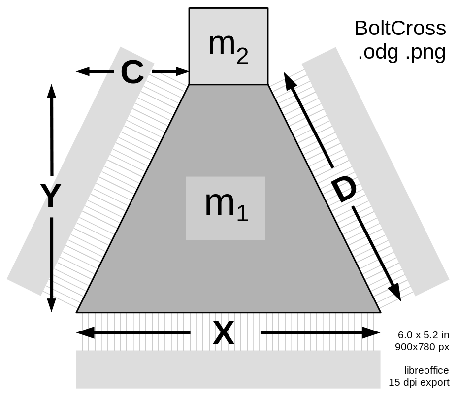
The density of 4% silicon transformer steel is 7.65 g/cm³, so A₁, the cross section of the area M₁, is A₁ = 0.65 cm² = 6.5e-5 m².~~~ A₁ = (A-C)×B .
Deflection Mode
In deflection mode, an electromagnet pole (shown at the bottom of this diagram) pulls the rotor towards it, with near-saturation flux density B_{max} , perhaps 1.8 Tesla. The material will be strongly saturated and with considerable hysteresis at this field strength; that actually helps regulate the deflection force.
The deflection field "entering" at the bottom exits at the two diagonal pole faces, with less flux density. The (atttracting) deflection force at the bottom is F_A ~=~ A ~×~ B_{max}^2 / 2 \mu_0 ~=~ A × 1.29 MPa . The flux at each diagonal face is B_D = ( A / 2 D ) B_{max} so the force at each face is F_D ~=~ D ~×~ B_D^2 / 2 \mu_0 ~=~ D ~×~ (A/2D)^2 B_{max}^2 / 2 \mu_0 ~=~ A^2/D × B_{max}^2 / 8 \mu_0 ~=~ A²/D × 0.16 MPa .

