|
Size: 2945
Comment:
|
Size: 3767
Comment:
|
| Deletions are marked like this. | Additions are marked like this. |
| Line 23: | Line 23: |
| || force on payload || 150 KN || || payload speed || 11 km/s || || track coil pitch || 0.11 m || || track field frequency || 100 KHz || || rotor speed || 14 km/s || || rotor coil pitch || || || rotor field frequency || || |
||<-2> End of acceleration and track conditions || || payload speed || 11 km/s || || power || 1.65 GW || extracted from rotor || || track coil pitch || 0.11 m || || track field frequency || 100 KHz || || rotor speed || 14 km/s || || rotor mass density || 3 kg/m || || rotor relative speed || 3 km/s || || rotor ΔV || 13.1 m/s || Slowdown under sled || || rotor time under sled || 33.3 ms || 100m / 3000 m/s relative || || rotor acceleration under sled || 393 m/s² || delta V / time || || rotor force per meter || 1179 N/m || acceleration times mass density || || rotor total force || 117.9 KN || the rest goes into the (rebounding?) track || || rotor coil pitch || || This varies along the track, longer at the end || || rotor field frequency || low || in ''rotor'' frame of reference || |
Rotor Lamination
Laminated launch loop rotors will have good magnetic properties and will rapidly disperse and oxidize in the atmosphere after a rotor-release catastrophe. Worst case, thin flakes survive and cut.
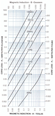
Metglas 2605SA1 looks good, higher temperature than 2605HB1M. datasheet downloaded 2017/02/11
Metglas 2605SA1 |
||||
Curie temperature |
395C / 668K |
|
saturation induction |
1.56 Tesla |
thickness |
23 μm |
|
density |
7.18 g/cm³ |
Thermal Expansion |
7.6 ppm/°C |
|
Iron vaporization temp |
3140 K |
Tensile Strength |
1 GPa |
|
Elastic Modulus |
100 GPa |
Iron |
85 to 95% |
|
2.5g/m³ |
|
Silicon |
5 to 10% |
|
3.0g/m³ |
|
Boron |
1 to 5% |
|
2,0g/m³ |
|
resistivity |
1.3 μΩ-m |
|
|
|
60 Hz and 1.4 T |
|
Induction at 80 A/m |
≥1.35 T |
|
Core Loss |
≤0.17 W/kg |
|
Exciting Apparent Power* |
1.1 (VA/kg) |
Naively, assume that the rotor is excited at 100 KHz and produces 150 KN of thrust against a payload moving at a relative speed of 3 km/s with a wavelength of 0.1 m, an excitation frequency of 30 KHz. Assume a similar synchronous frequency (it will actually be slightly lower). Assume a sled length of 100 meters.
End of acceleration and track conditions |
||
payload speed |
11 km/s |
|
power |
1.65 GW |
extracted from rotor |
track coil pitch |
0.11 m |
|
track field frequency |
100 KHz |
|
rotor speed |
14 km/s |
|
rotor mass density |
3 kg/m |
|
rotor relative speed |
3 km/s |
|
rotor ΔV |
13.1 m/s |
Slowdown under sled |
rotor time under sled |
33.3 ms |
100m / 3000 m/s relative |
rotor acceleration under sled |
393 m/s² |
delta V / time |
rotor force per meter |
1179 N/m |
acceleration times mass density |
|| rotor total force || 117.9 KN || the rest goes into the (rebounding?) track ||
rotor coil pitch |
|
This varies along the track, longer at the end |
rotor field frequency |
low |
in rotor frame of reference |
Failure and oxidation
Iron has a specific heat of 25.1 J/(mol·K), vaporizes at 3140K, and has a heat of vaporization of 340 kJ/mol . Naively, to go from 400K to vaporization requires 410 kJ/mol or 16 MJ/kg . The rotor moves at 14 km/s, the kinetic energy is 98 MJ/kg, so there is more than enough energy to vaporize the rotor foil and ignite it. Further study and experimentation needed; perhaps most of the energy will end up heating the surrounding air, and the foil will fragment and fall to the ocean surface and then the sea floor.

