|
Size: 4388
Comment:
|
Size: 4433
Comment:
|
| Deletions are marked like this. | Additions are marked like this. |
| Line 40: | Line 40: |
| [[ attachment:tr04.c | Here is the source ]] , and you will need [[ http://www.libgd.org/ | libGD ]] and apngasm. |
[[ attachment:tr04.c | Here is the source ]] , and you will need [[ http://www.libgd.org/ | libGD ]] and [[ http://apngasm.sourceforge.net/apngasm | apngasm ]]. |
Tensile Truss
The following calculation is for a tensile cable form of a triangular truss, similar to a Warren truss, though we will use 63.4:63.4:53.2 degree triangles rather than equilateral triangles. That makes the wavelength of the truss equal the spacing - nothing magic about that, besides making the calculations a bit easier.
Simplified Truss
Assume 28% of the support weight of the 80km 7kg/m track is devoted to tension on hanging pulldown cables to the surface, or 19 N/m of track. With an 80km support length, a 19 Newton cable weighs 0.24 g/m .
Assume that 5% of the weight the 7 kg/m launch track is devoted to the horizontal truss cables. If the cables are Kevlar, stressed to a support length of 80km, then the weight is 0.35 kg/m (cross section 2.4E-4 m2) and the tension is 280 kN. The curvature of this tension reduces the track lift by 4.4 g/m, one percent of the truss cable weight, negligible.
Assume that the truss is divided into a larger and smaller spreader section, the first with a wavelength and spacing of one meter, the second with a wavelength and spacing of 500 meters. Both sections pass the full force of the pulldown cables. Let's assume that 25% of the tension (70kN) is in the top lateral, 25% in the lateral 1 meter down, and 50% (140KN) is in the lateral 500 meters down.
The longitudinal speed of sound in Kevlar is 9.3 kilometers per second. The hypotenuse on 1 meter truss is 1.12 meters, so the speed of sound from the top to the bottom of that truss is 120 microseconds. The hypotenuse of the 500 meter truss is 60 milliseconds. We will hang moving actuators on the larger truss cables, as well as laser distance measuring transmitters at the joints.
The top stringers will weigh 0.5*1.25*0.24 g/m, or 0.15 grams per stringer. The lower stringers (both longer and more widely spaced) will weigh 5002 times that, or 100 kilograms each.
The bending moment of the top truss is E A W^2/2 , where W is the width of the truss. A = 6E-5 m2, W=1m, and E = 124 GPa, so the bending moment is 4E7 N/m2 for the top truss. For the stiff rotor, the speed of sound in iron is C_{FE} = 5200m/s, the radius of the rotor is 0.05m, and the mass per length is 3 kg/m . The rotor stiffness is $ ( C_{FE} m_r R2 / 2 ) = 2.5E4 N/m2^, so the 1M truss section will stiffen the track/rotor system by 1600X, increasing the minimum perturbation wavelength by the square root of that, or 4X. This will hold true down to time periods of 120 microseconds or so, the prop time through the first truss
For the bottom truss, the area is doubled and the width is 500X, so for A=1.2E-4, W=500m, and E= 124 GPa, resulting in a bending moment of 1.9E11 N/m2, 7.5E6 times stiffer than the first truss to large scale bending. That increases the minimum perturbation wavelength (compared to just the rotor) by 2700x .
Laser Distance Measurement
While stability is helpful, the main thing the lower truss does for us is increase the baseline for laser distance measurement.
MORE LATER
|
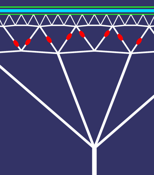
This shows one potential form of the double truss. The lower truss is actually much wider, and the bottom connection to the ground-connected cable is actually far lower than shown. The bottom rail of the truss is 500 meters below the track, and the bottom connection is at 20km altitude, perhaps 60 km below the eastbound launch track. This does not show any cable redundancy - we must make sure that one or two sheared cables do not deflect the track into the rotor. |
Simplified Truss Simulation
Here's an animation of what a tension truss does given sinusoidal displacement. The perturbations are greatly exaggerated, and the forces and angles are only approximate. Gray is initial tension loading, red is extra tension, cyan is relaxed tension. This needs a much better simulation with accurate numbers. Overall tension goes up as the square of the amplitude divided by the wavelength - the amplitudes on a real launch loop will be very small.

Here is the source , and you will need libGD and apngasm.
MORE LATER

