|
Size: 1451
Comment:
|
← Revision 21 as of 2022-10-17 08:54:42 ⇥
Size: 2044
Comment:
|
| Deletions are marked like this. | Additions are marked like this. |
| Line 3: | Line 3: |
| Sorry, ancient shockwave flash, your web browser may complain. I will upgrade these animations to MPEG when I upgrade this website (and learn how). |
-------- {{ attachment:Rotor02OpenEnd.png | | width=768,height=576 }} {{ attachment:Rotor02OpenSide.png | | width=768,height=576 }} |
| Line 7: | Line 8: |
| <<EmbedObject(Rotor02OpenEnd.swf,play=true,loop=true,width=768,height=576)>><<EmbedObject(Rotor02OpenSide.swf,play=true,loop=true,width=768,height=576)>> -------- |
|
| Line 10: | Line 9: |
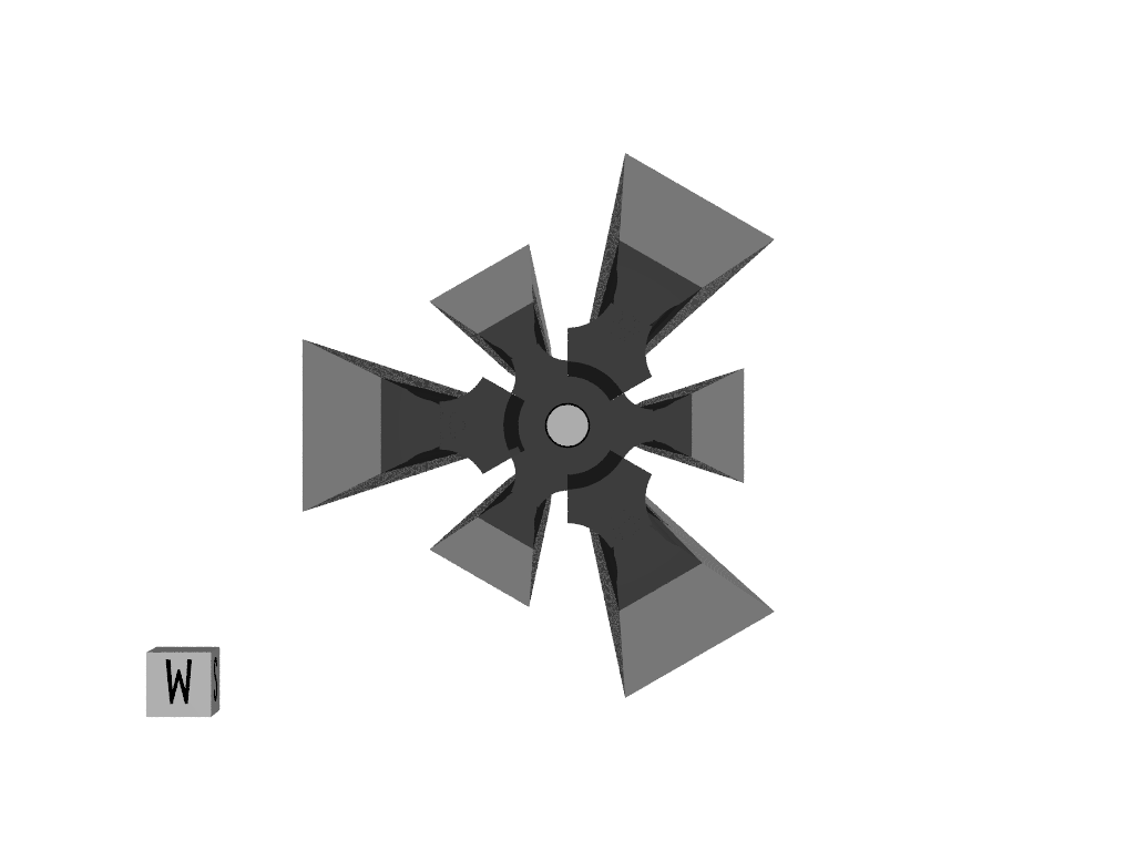
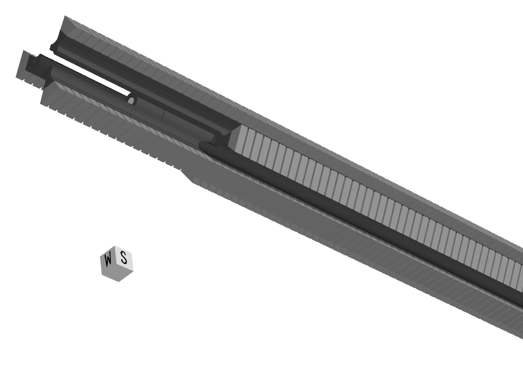
| These animations show how the rotor bolts disassemble before rotating and passing through the deflection magnets. The gray represents transformer laminations, which will actually be quite thin with just enough insulation between them to electrically isolate the laminations and allow field penetration. |
These animations are not to scale. |
| Line 15: | Line 11: |
| The six longitudinal gaps will be just wide enough to admit a stationary winding, plus some enough tolerance to keep the winding from touching the hypervelocity rotor. The only way this will work is if the windings dip inwards briefly before and after sled passage, are maintained exactly in the center (somehow) by eddy currents, and of course the 14 km/s rotor moves in a very high vacuum. |
They qualitatively illustrate how the rotor bolts disassemble before rotating and passing through the deflection magnets. The gray trapezoids represent transformer laminations, which will actually be quite stacks of thousands of thin sheets of audio transformer steel, with just enough insulation between them to electrically isolate the laminations and allow field penetration. |
| Line 21: | Line 13: |
| This does not show the longitudinal copper windings and optical SCRs wrapped around the poles, which pin the magnetic excitation field in the rotor, and subsequently provide motor thrust for the passage through the motor windings |
As a wild guess, the bolt sections will be 10 meters long, and the diameter perhaps 4 centimeters. They will be spaced perhaps a centimeter apart (between the ends) longitudinally at 80km altitude (perhaps overlapping), increasing to 5 centimeters near the surface as the rotor descends and increases velocity (same mass flow rate, Bernoulli effect written in iron). |
| Line 25: | Line 15: |
| A magnetic field is synchronously imprinted on the rotor; the "slip" will be small, and the risetime of the field will be around 200 microseconds. |
The six longitudinal gaps will be narrower than shown; just wide enough to admit a stationary winding, plus some enough tolerance to keep the winding from touching the hyper-velocity rotor. The only way this will work is if the windings dip inwards briefly before and after sled passage, are maintained exactly in the center (somehow) by eddy currents. The 14 km/s rotor moves in a very high vacuum, of course. If windings are damaged, they won't be commanded to "dip" and there will be a sub-millisecond interruption in thrust. Flux is circumferential. This animation does not show the longitudinal copper windings and optically-triggered SCRs wrapped around the poles, which pin the magnetic excitation field in the rotor, and subsequently provide motor thrust for the passage through the motor windings. A magnetic field is synchronously imprinted on the rotor; the "slip" will be small, and the rise0-time of the field will be around 200 microseconds. Animations updated to APNG animation in June 2021. Will attach povray source files Real Soon Now. |
Rotor Animations


These animations are not to scale.
They qualitatively illustrate how the rotor bolts disassemble before rotating and passing through the deflection magnets. The gray trapezoids represent transformer laminations, which will actually be quite stacks of thousands of thin sheets of audio transformer steel, with just enough insulation between them to electrically isolate the laminations and allow field penetration.
As a wild guess, the bolt sections will be 10 meters long, and the diameter perhaps 4 centimeters. They will be spaced perhaps a centimeter apart (between the ends) longitudinally at 80km altitude (perhaps overlapping), increasing to 5 centimeters near the surface as the rotor descends and increases velocity (same mass flow rate, Bernoulli effect written in iron).
The six longitudinal gaps will be narrower than shown; just wide enough to admit a stationary winding, plus some enough tolerance to keep the winding from touching the hyper-velocity rotor.
The only way this will work is if the windings dip inwards briefly before and after sled passage, are maintained exactly in the center (somehow) by eddy currents. The 14 km/s rotor moves in a very high vacuum, of course. If windings are damaged, they won't be commanded to "dip" and there will be a sub-millisecond interruption in thrust.
Flux is circumferential. This animation does not show the longitudinal copper windings and optically-triggered SCRs wrapped around the poles, which pin the magnetic excitation field in the rotor, and subsequently provide motor thrust for the passage through the motor windings.
A magnetic field is synchronously imprinted on the rotor; the "slip" will be small, and the rise0-time of the field will be around 200 microseconds.
Animations updated to APNG animation in June 2021. Will attach povray source files Real Soon Now.
