|
Size: 5025
Comment:
|
Size: 5702
Comment:
|
| Deletions are marked like this. | Additions are marked like this. |
| Line 36: | Line 36: |
| Thermodynamically, there is a lot of potential and kinetic energy in the system which for a passive stabilization system will tend to equipartition into all accessible vibrational modes. The condition of stability becomes a dynamic equality for a thermal system, because growing vibrational states increase the tension in the track until the equality is true. | The fundamental condition of stability for a launch loop is that the track tension is greater than the rotor density times the square of the rotor velocity. |
| Line 38: | Line 38: |
| Interestingly, if you reverse the sign of the condition of stability, it becomes the condition which must hold for the loop to have any ability to loft itself. | Thermodynamically, there is a lot of potential and kinetic energy in the system which for a passive stabilization system will tend to equipartition into all accessible vibrational modes. The condition of stability becomes a dynamic equality for a thermal system, because growing vibrational states increase the tension in the track until the equality is true, and this is exactly what can be seen in the above animation. |
| Line 40: | Line 40: |
| This is why active stabilization is needed. | Interestingly, if you reverse the sign of the condition of stability, it becomes the condition which must hold for the loop to have any ability to loft itself, which is of course a problem, and this is why active stabilization is needed. |
| Line 47: | Line 47: |
| Setting up the launch loop in a helical structure has the advantage that it provides tension for guy wires between tracks, creating a stiff structure which resists bending. Further, with adjustable counterweights moving along the guy wires, curvature can be induced in the track which can resist wind loads, as in the system proposed by John Knapman. | Setting up the launch loop in a helical structure has the advantage that it provides tension for guy wires between tracks, creating a stiff structure which resists bending. It should be noted that the loop in the first simulation can be stabilized if the shear modulus of the track is increased to about a factor of 1000 greater than steel. Further, with adjustable counterweights moving along the guy wires, curvature can be induced in the track which can resist wind loads, as in the system proposed by John Knapman. The only unphysical parameter used in the above simulation is the spring constant for the guy wires, which is artificially high, in order to simulate the actions of an active wire tensioning system. |
| Line 50: | Line 54: |
| The software is only an early alpha version, and has a number of issues. For the helical track, the initial state is clearly "hot" and it is not stable in the long term. The loop is initally in a state without cable tension, whereas a stable state necessarily includes energy in vibrational modes, due to thermodynamics, which translate into tension. The guy wires are not tensioned correctly, the rotor mass is not balanced right, and there might be an issue with changes in angular momentum along the helix. | The software is only an early alpha version, and has a number of issues. For the helical track, the initial state is clearly "hot" and it is not stable in the long term. The loop is initially in a state without cable tension, whereas a stable state necessarily includes energy in vibrational modes, due to the thermodynamics, which translates into tension. Further, the guy wires are not quite tensioned correctly, the rotor mass is not balanced right, and there might be an issue with changes in angular momentum as the rotor moves along the helix. |
| Line 52: | Line 56: |
| Even so, it is possible to get an impression of the thermal behaviour of the system. | Even so, it is possible to get an impression of how the thermal behaviour of the system works. |
| Line 61: | Line 65: |
Like everything else on this wiki, a work in progress.
Numerical Model
The model presented here is essentially a division of the track into point-like segments where the track and rotor is treated as a composite object, and updates are by the Euler method. Since the simulation is macroscopic, it is justified to treat the launch loop as an infinitely thin track, with very little resistance to bending, and with no divergence between sheath and rotor at any location. This implies that the active control system employed to stabilize the model can only influence the speed of the rotor as long as no guy wires are employed.
Each composite sheath and rotor segment has the following attributes: A static track mass, a variable rotor mass, a center of mass position, and a combined linear momentum (which is stored numerically as a center of mass velocity).
Movement of the center of mass is governed by Newtons laws. There are 3 external forces that act on the segment:
1. Gravity.
2. The wind.
3. The force between neighbouring segments which arises because they are connected. This connection is modelled as a Kelvin-Voigt material (in other words, a spring). The speed of sound in this connection (in other words, the track itself) is assumed to be 3000 m/s, as for steel. From this, the spring constant and damping constant can be calculated:
Speed of wave in spring: v = sqrt(k*L/rho)
Damping ratio: eta = c/2/sqrt(m*k)
Damping force: F = -c*v
Spring force: F = -k*x
It may seem natural to also include the force between the sheath and the rotor, since this force keeps the sheath aloft and bends the rotor towards the ground, but it is purely an internal force, and so should not be included in a composite model.
For every time step of the simulation, the center of mass of each segment is moved eastward inertially, because the linear momentum of the composite is dominated by the rotor. However, it is also moved westward, because the responsibility for accounting for a stretch of rotor (the length of which depends on the rotor speed and the size of the time step) is moved from each segment to its eastward neighbour. The end result is that the segments move very little if the system is stable.
Angular Momentum
It could be argued that the angular momentum of each segment should be accounted for alongside the linear momentum. Segments are not point-like, after all. However, any error introduced by omitting the angular momentum is reduced when the resolution is increased, since a string of point masses have aproximately the same angular inertia as a line mass.

For the simulations shown here, the speed of the rotor at apex is 2000 km/s, 4200 km/s at ground, rotor density is 1 kg/m, and track density is 10 kg/m.
Stability Issues
The fundamental condition of stability for a launch loop is that the track tension is greater than the rotor density times the square of the rotor velocity.
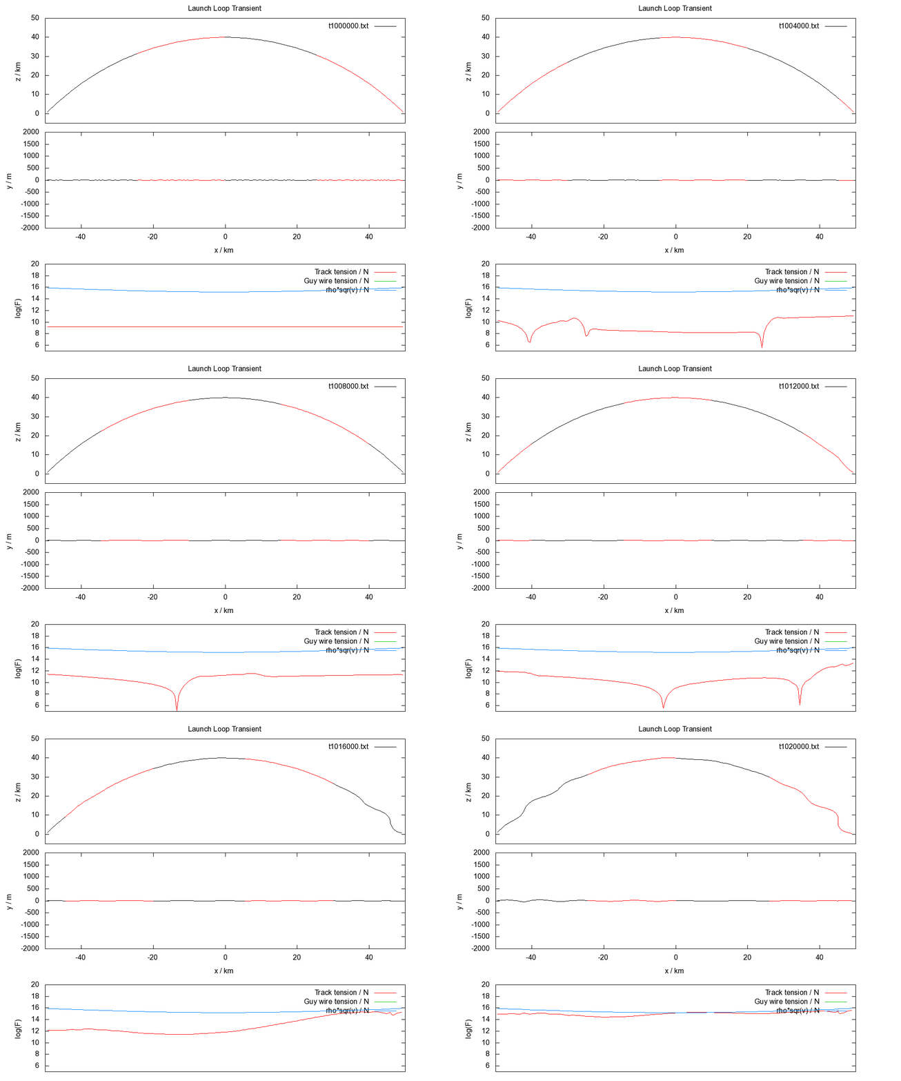
Thermodynamically, there is a lot of potential and kinetic energy in the system which for a passive stabilization system will tend to equipartition into all accessible vibrational modes. The condition of stability becomes a dynamic equality for a thermal system, because growing vibrational states increase the tension in the track until the equality is true, and this is exactly what can be seen in the above animation.
Interestingly, if you reverse the sign of the condition of stability, it becomes the condition which must hold for the loop to have any ability to loft itself, which is of course a problem, and this is why active stabilization is needed.
The tendency of the track to first destabilize near the ground is due to the higher speed of the rotor there.
Helical Structure

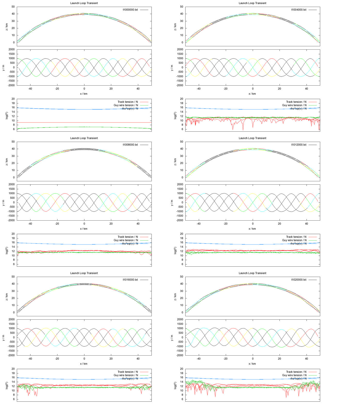
Setting up the launch loop in a helical structure has the advantage that it provides tension for guy wires between tracks, creating a stiff structure which resists bending. It should be noted that the loop in the first simulation can be stabilized if the shear modulus of the track is increased to about a factor of 1000 greater than steel.
Further, with adjustable counterweights moving along the guy wires, curvature can be induced in the track which can resist wind loads, as in the system proposed by John Knapman.
The only unphysical parameter used in the above simulation is the spring constant for the guy wires, which is artificially high, in order to simulate the actions of an active wire tensioning system.
Current Issues
The software is only an early alpha version, and has a number of issues. For the helical track, the initial state is clearly "hot" and it is not stable in the long term. The loop is initially in a state without cable tension, whereas a stable state necessarily includes energy in vibrational modes, due to the thermodynamics, which translates into tension. Further, the guy wires are not quite tensioned correctly, the rotor mass is not balanced right, and there might be an issue with changes in angular momentum as the rotor moves along the helix.
Even so, it is possible to get an impression of how the thermal behaviour of the system works.
Future work
- In order to validate the model, the macroscopic behaviour of the system must be independent of the resolution of the simulation.
- Further, energy accounting must be included, because the degree to which energy is conserved is an imortant metric of the quality of the model.
Code
C++ source file: main.cpp
Cygwin script for plotting data: LaunchLoopScript
