|
Size: 2079
Comment:
|
Size: 1506
Comment:
|
| Deletions are marked like this. | Additions are marked like this. |
| Line 1: | Line 1: |
| = New Rotor for Launchloop 2.0 = | = New Rotor for Launchloop 2.1 = |
| Line 3: | Line 3: |
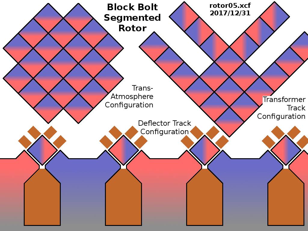
| || {{ attachment:rotor2.png }} || The new rotor will use a Kevlar-stiffened laminated transformer steel rotor and a vertical Kevlar bar with embedded permanent magnets. Kevlar is stronger and stretchier than iron or steel, so expansion joints are not needed to accomodate the stretch caused by the descent from 100 km altitude to the ground. The Kevlar backbone will provide enough stiffness to reduce "waviness", which allows for increased control circuit spacing for the ambit magnets.<<BR>><<BR>>[[attachment:rotor2.svg | SVG drawing made with Inkscape]]<<BR>><<BR>> [[attachment:rotor2.png | png drawing for download]]|| | || {{attachment:rotor05.png }} || The new rotor is composed of "block bolts", 5 millimeter square, perhaps 10 meter long blocks of laminated transformer steel, wrapped in thin aluminum wire hoop motor windings, and coated with amorphous diamond. [[attachment:rotor05.png | png drawing for download]]|| |
| Line 5: | Line 5: |
| The Kevlar bar may be hollow with struts, with the magnets inside. All structures will be diamond/carbon coated to reduce spalling cascades. | The bolts are spread out for travel around the high radial acceleration deflector magnets, bunched into a minimum cross section for passage up and down narrow tubes for passage through the turbulent and windy atmosphere, and reshaped into a V (or flat H) configuration to act as a velocity transformer rotor on the acceleration path. |
| Line 7: | Line 7: |
| The laminated metal crossbar can be deflected with magnets on the bottom, or a little less magnet from the top. The bottom will be turned sideways to face the inside "pivot" of the ambit magnets. | The individual streams of bolts are "woven" and "unwoven" as they pass through the system. If there are 21 bolts in parallel, they will follow a "mobius path" so they are positioned in each of the 21 positions consecutively. |
| Line 9: | Line 9: |
| The magnets fly past (diamond/carbon coated) aluminum coils, part of a high speed motor/generator system for the VelocityTransformer. The scale is on the order of 10 centimeters. | All bolts are bar-coded, and the outer bolts are microscopically measured with laser-flash-illuminated ultra-high-speed cameras on every passage of each end. Bolts that appear to be damaged are swapped with fresh bolts launched from east return station and accelerated to rotor speed; the damaged bolts are ejected from west return station ... either slowed to fall into the ocean, or launched full speed into Earth escape. |
| Line 11: | Line 11: |
| With transformer coupling, we need not run the rotor a lot faster than the vehicle; the relative speed is necessary only so the power extracted by the vehicle is not too high near exit speed. If the maximum launch speed is limited to Earth escape, about 10.7 km/s, that should be able to reach any Earth orbit, sending payload and passengers to interplanetary vehicle assembly orbits. | |
| Line 13: | Line 12: |
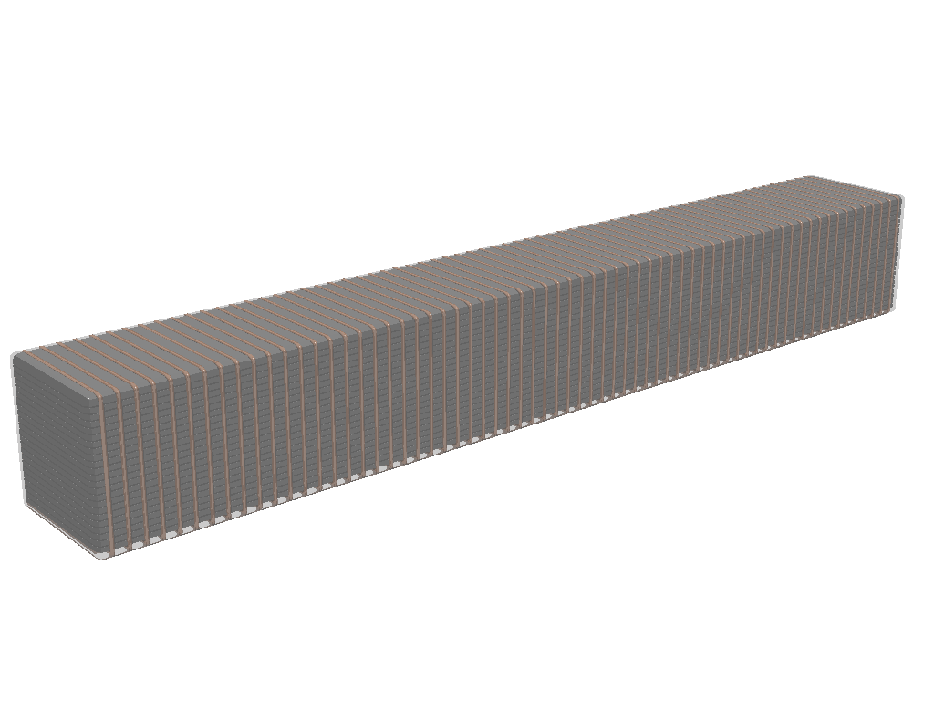
| If we lower the rotor speed to 12 km/s, that reduces ambit radius by a factor of 0.62 . That will require a more massive rotor (5 kg/m) for the same support force, but the iron portion can be wider so the ambit radius stays the same. Very high orbit payloads can be less massive and put less drag on a more massive rotor, though the delta V on the rotor from one 10.6 km/s, 5000 kg, 3 gee acceleration payload is only 20 m/s. Delta is 14 m/s for the original 14 km/s rotor. | {{attachment:Block_bolt3.png }} [[attachment:Block_bolt3.png | png drawing for download ]] [[attachment:Block_bolt3.pov | Povray code for download ]] |
New Rotor for Launchloop 2.1
|
The new rotor is composed of "block bolts", 5 millimeter square, perhaps 10 meter long blocks of laminated transformer steel, wrapped in thin aluminum wire hoop motor windings, and coated with amorphous diamond. png drawing for download |
The bolts are spread out for travel around the high radial acceleration deflector magnets, bunched into a minimum cross section for passage up and down narrow tubes for passage through the turbulent and windy atmosphere, and reshaped into a V (or flat H) configuration to act as a velocity transformer rotor on the acceleration path.
The individual streams of bolts are "woven" and "unwoven" as they pass through the system. If there are 21 bolts in parallel, they will follow a "mobius path" so they are positioned in each of the 21 positions consecutively.
All bolts are bar-coded, and the outer bolts are microscopically measured with laser-flash-illuminated ultra-high-speed cameras on every passage of each end. Bolts that appear to be damaged are swapped with fresh bolts launched from east return station and accelerated to rotor speed; the damaged bolts are ejected from west return station ... either slowed to fall into the ocean, or launched full speed into Earth escape.


